r/PrintedCircuitBoard • u/Megadonuto • 20h ago
This is my first time making a PCB board. I am making glasses for the blind that have a laser rangefinder and a microphone and
8
Upvotes
r/PrintedCircuitBoard • u/Megadonuto • 20h ago
r/PrintedCircuitBoard • u/raschkebab • 7h ago
Put together a PCB for detecting with a colour sensing and broadcasting via bluetooth. PCB has been manufactured, but there is no detection when plugging into PC. The lower section of the PCB is intended to be cut away after first use of uploading code via the micro usb. Using Nordic for the bluetooth mcu.
r/PrintedCircuitBoard • u/wejn • 13h ago
Hoi folks,
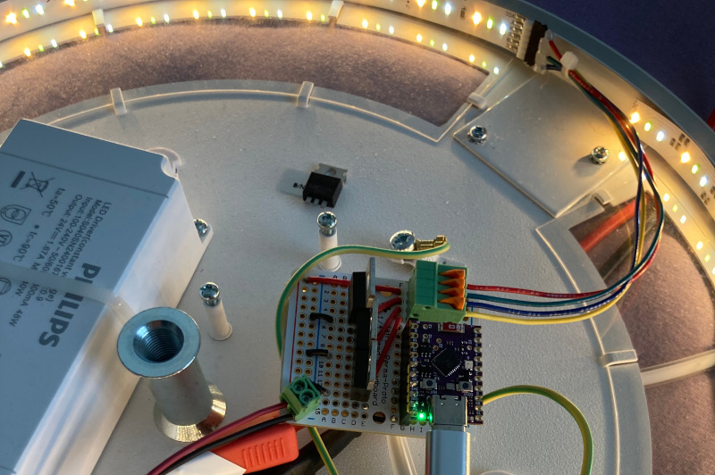
I'm trying to make my own Zigbee LED light to replace Hue driver (long story).
Would anyone be willing to give me constructive feedback on this, before I send it to have it fabbed?
Repo: https://github.com/wejn/e32wamb-pcb (KiCAD project is in project dir).
Shots:


Now, the Idea is that J1 takes 24V in, which goes to common anode LED strips connected via J2 and J3 (initially just J2). In order to power the XIAO ESP32-C6 I've cobbled together a buck using AP63203 (hopefully I've got that layout right). The LED driver is simple N-mosfet, exactly the way Hue does it.
Similar frankenstein (sans the buck) works on a proto devboard, so I'm somewhat convinced this isn't completely stupid (well, sans the buck, trace sizes, layout, etc).
FTR, the mounting holes are in a place that's forced by external circumstances (already existing mount posts), so can't move those. Which is why I struggled with the layout (board space) somewhat.
Please be gentle (but firm), it's my first "real" board, and I ain't no EE.
r/PrintedCircuitBoard • u/voicubabiciu • 2h ago
Hey everyone!
I’m a beginner and recently started working on a small electronics project. This is the biggest schematic I’ve made so far, and I’m really excited about it!
The idea is to build an ESP32-based PoE board with USB, and this schematic is my first step — more of a test board to validate things before expanding the project further.
I’ve uploaded the schematic, and I’d really appreciate it if someone with more experience could take a look and let me know if there are any obvious mistakes, bad practices, or suggestions for improvement. I’m still learning, so any feedback is more than welcome!
Thanks a lot in advance! 😊

r/PrintedCircuitBoard • u/Mees_ • 23h ago
Hi All, i'm working on a simple USB C PD powered board that switches a 12V/20W heating pad. It's the first time i'm working on the component level instead of breakout boards. It incorporates a 1-wire thermal probe, i2c oled and Seed Studio Xiao C6 to connect to a zigbee network and drive everything.
I was about to order the board when i found that i had incorrectly hooked op the mosfet and used a wrong shunt resistor for the current sensing part, those should be fixed now, but it made me a bit anxious.
It's a 4 layer board with the "high" power traces on top, 5v, gnd, and signal traces going down.
I was wondering if the VBUS would be better as a zone instead of a wide trace.
Any input would be highly appreciated!
r/PrintedCircuitBoard • u/Unhappy_Tourist_8224 • 11h ago
Hi everyone, my last post got taken down because of a black background, I'm hoping for a review of my PCB, a 12V 3A board which will power a water pump (rated 12V 3A) at certain times during the day.


r/PrintedCircuitBoard • u/Spiritual_Dealer_588 • 3h ago
Hi, I am creating a flight computer to be used in a rocket and drone. The rocket will only have servo outputs, but the drone will be controlling both ESCs and servos. I want the options of powering the board and outputs from USB, battery, or BEC (5V linear regulator of ESC).
The cases for power input:
BEC only
BEC with USB
Battery only
Battery with USB
USB only
I am using a diode multiplexer where the highest voltage source is selected, and this goes through the INA260 power monitoring IC before powering the 3.3V and 5V buck converters.
For the output power, I am using 2 jumpers to select between BEC, 5V buck converter, and battery sources. However, I don't know if the jumper caps can handle enough current for all the servos. The diode on outputs 2-8 ensure that any BECs connected to those outputs don't backfeed into each other, and only output 1's BEC will provide power. When output 1 is not an ESC, it can be connected to the rest of the outputs 2-8 through another jumper to connect it to external power.
For the signal voltage, I want to be able to choose between 3.3V and 5V. I am currently using 2 jumpers, but I'm wondering if there's a better way. Note that I need to choose between 5V buck converter voltage and BEC voltage because when the BEC powers the 5V buck converter, the output will be less than 5V.


r/PrintedCircuitBoard • u/incogneaters • 8h ago
Hi all!
I decided to quickly cook up a PCB to take 3.3 volts from an ESP32 3.3v pinout (in this case a Seeed Studio XIAO ESP32S3 CAM unit) to power a TLV62568DBVR and distribute the proper voltage/amperage to each IR LED 14 x XINGLIGHT XL-3216HIRC-850). Additionally, this same PCB on a separate circuit/section takes a 3.7 volt battery input and filters/protects the ESP32 before the ESP32 actually receives the battery input via its BATT+/- pads.
Overall I haven't finished the silkscreen and other finer details because I previously kept focusing on that stuff before actual functionality. I thiiiiiiiiink I have everything right/done correctly electrically/layout-wise, but figured I'd ask some of the veteran/pros here before sending this for manufacturing for myself/a few friends.
If you see any errors or issues with what I want to do/my layout/etc.........by all means let me know! I plan on making future PCB-related projects and would love to know what to do right/what I did wrong with this project to avoid the same issue in future projects. Admittedly, I am TERRIBLE at doing the schematics-side of things. I even built the project and PCB visually before even touching schematics.
P.S. I'm new here (and to designing PCBs in general), so if I do/did something wrong rules-wise, I apologize in advance!
r/PrintedCircuitBoard • u/JizosKasa • 14h ago
Hi everyone, I'm working on my very first PCB for the Raspberry Pi 3B+, and I was hoping someone could take a look at the connections I've made.
I’d like to know if they’re correct or if there are any issues I should be aware of. The goal of this project is simply to connect an OLED screen, an LED, and a tactile button, each as standalone components, meaning they shouldn't be connected to each other within the circuit.
Since this is my first time using a program like EasyEDA (and my first real attempt at anything electronics related) I'm finding it a bit challenging to tell if I’ve done things properly. Any guidance would be greatly appreciated!
Here's the link: https://oshwlab.com/jizoskasa/project_1
r/PrintedCircuitBoard • u/frequency_abovetime • 13h ago
I have those switches: https://www.taydaelectronics.com/datasheets/files/A-4567.pdf
what hole size I need for those switch pins? (pins size are: 0.80 mm (W) × 2.00 mm (L))
will hole of 2.4mm will work? how to calculate it?
r/PrintedCircuitBoard • u/circuitshack • 11h ago
How to import a schematic of a IC given in its datasheet into Altium schematic.Is there any better way to do this rather than creating a separate schematic?